written by: Ing. Francesco D'ANGELO
1 INTRODUCTION
In my career as a designer I happened, not infrequently, to run into a project deficient and not in compliance with UNI CEI and formal requirements relating to the design documentation must have.
For this reason I decided to write the following article which will describe initially UNI that must be applied to project drawings such as the sizes of the sheets unified or proper placement of the title block. A follow will illustrate the CEI to be applied for the representation and description of a graphic design of electrical installations. Many times I happened to find, for example, wrote Kw; a serious mistake because it does not fully respects the Presidential Decree of 12 August 1982 n. 802 "Implementation of EEC Directive 80/181 relating to units of measurement" that requires the use of the international system of quantities and units of measure.
2 DOCUMENTATION PROJECT
For project is a set of coordinated activities to achieve a certain goal (the project) that meets certain specifications and standards in the field of time-definite and limited costs or limit within a certain budget.
The main characteristics of a project are:
objectives defined
Each task has a specific finalizing the result of which is essential to achieve the objective.
uniqueness
Each project, although similar to other previously developed is unique.
temporariness
Each project has a start date and an end pre-organization of the project.
multidisciplinary
Normally a project requires different skills that all converge toward the same goal.
limited resources
A project requires a certain availability of resources for each activity.
Project management, on the other hand, involves the planning and monitoring of the project and includes the following elements:
project planning
- definition of the requirements of the job;
- definition of the quantity and quality of work;
- definition of the necessary resources.
monitoring of the project
- detection of development;
- comparison of results with those expected;
- adjustments to be made.
The project manager (PM) is the point of reference for project management as it has the task of managing the entire lifecycle of the project. During all phases of the design the PM plays a dual role as the one responsible for the achievement of the objectives within the time and cost and fixed interface between the client and the design team.
The project and therefore the project documentation, ie the set of technical documents and graphics that make up the project, must necessarily be in compliance with UNI and CEI. In fact, the paragraph 3 of art. 5 of DM 37/08 indirectly refers only to guide CEI 0-2 on the drafting of the project; For this reason, the guide CEI 0-2 assumes a legal value.
3 FORMAL REQUIREMENTS UNI
The table below shows the UNI on setting graphics boards:
UNI EN ISO 5457: available formats and graphic elements of the chart;
UNI 938: folding sheets;
UNI EN ISO 128-20: types, thickness and application of the guidelines;
UNI EN ISO 3093-1: Writing on the drawings (minimum height characters);
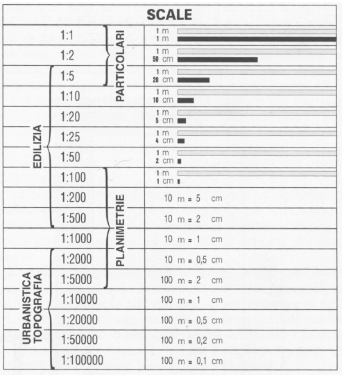
UNI EN ISO 5455: Unified stairs;
UNI EN ISO 129: dimensions;
UNI 3975: elevations
UNI EN ISO 7200: title block (cartouche).
The following table shows the common formats according to the UNI EN ISO 5457.
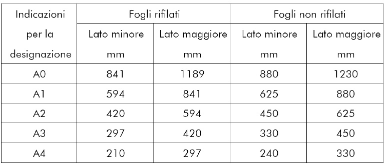
Generally the use of formats is the following:
A4 technical documents (reports, specifications, calculations);
A0 to A3 drawings (floor plans, single-line diagrams).
The UNI EN ISO 5457 also allows the use of special formats elongated obtained from the basic formats, which are listed in the table above, extending n times its value.
The UNI 938 defines the bending of a graphics tablet that can be performed in 2 different ways:
flapless of attack;
flap on the left side of attack for binding in installments.
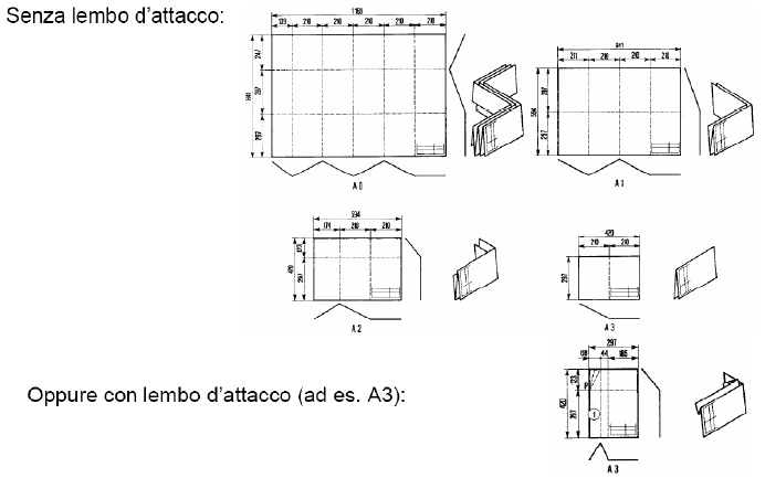
The table below shows the description of the first folding method:
"Starting from the right performing successive parallel vertical folds all spaced 210 mm, the first back and the next and so forth alternately back and forth leaving any last remnant of smaller width. Starting with the underside of the sheet thus obtained, performing the horizontal bending forward and back. "
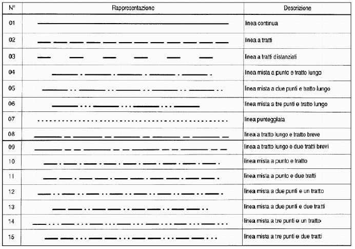
The following figure shows the types, thickness and application of lines as defined by the UNI EN ISO 128-20:
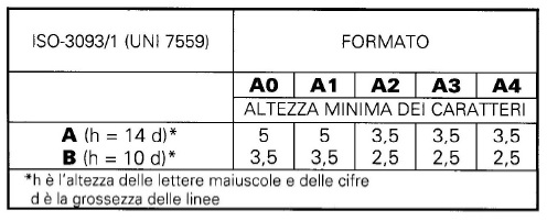
The UNI EN ISO 3093-1 defines the minimum height of the font according to the size of the paper:
The UNI EN ISO 5455 defines unified scale. The following figure shows the stairs unified and usage:
The UNI EN ISO 7200 indicates the minimum information to be reported and the location, which should be in the bottom right corner of the title block (cartouche):
- professional practice;
- the client;
- title of the project;
- design argument;
- scale of representation;
- number of the table.
4 ELECTRICAL INSTALLATIONS
4.1. CEI
The symbols to be used in the field of electrical systems are encoded by the Technical Committee 3 adopted by the IEC and CENELEC and IEC, such as:
CEI EN 60617-3 conductors and connection devices;
CEI EN 60617-7 equipment and control devices and protection;
CEI EN 60617-8 measuring instruments, lamps and signaling devices;
CEI EN 60617-11 patterns and architectural and topographical installation plans.
As a tool to be used for the representation of the different connections that allow electrical components to operate using the wiring diagram. The representation of a circuit can occur through the following wiring diagrams:
- single-line diagram: two or more conductors are represented by a single line and the signs graphs provide an indication of the number of conductors in each line;
- schema multi-wire: complete representation of an electrical circuit.
In the context of circuits, and then patterns (single wire and stranded) can be distinguished:
- power circuits: circuits whose job is to feed the organs of power;
- auxiliary circuits: circuits supplying coils (contactors, relays) that serve the movement and / or signaling.
In the diagrams is always advisable to identify the electrical components so that they are uniquely identified. The CEI 3-62 establishes an identification code composed of four parts:
Part 1 function code (prefix "=") identifies the functional element of the electrical system;
Part 2 location code (prefix "+") specifies the physical location of the component;
Part 3 product code of the component (prefixed with "-") indicates the type of component;
Part 4 terminal code (prefix ":") identifies the component terminals (optional).
For example the identification code = QMT1 + CB2-Q6: 12 indicates the terminal 12 of the switch -Q6 belonging to the field of medium voltage QMT1 located in the electric cabin CB2.
4.2. UNIT OF MEASURE
The activity measurement is an operation that you perform on a daily basis and often in an instinctive way: measure the weight of the goods that you buy, the speed at which you are traveling, you look at the clock to know what time.
We define, therefore, measures the process by which you match a number to a physical quantity. Make a measurement means assigning a physical quantity (eg. Mass, time, length, etc.) a numerical value that indicates how many times the unit of measure chosen, to which you assign a value of one is contained in the physical quantity to be measured. Each physical quantity will be characterized by a number (measurement) followed by a symbol which resembles the unit of measure used for the measurement.
In order to limit the use of the reference sample for the measurement units these are divided into:
- units of the fundamental quantities;
- units of derived quantities.
For the units derived from those fundamental it introduces the concept of dimension, namely the power with which the fundamental unit of measurement appears in the unit of measurement derived, that is, in the word size denotes the physical nature of a magnitude. The symbols that are used to indicate the size of a magnitude are enclosed in brackets. Dimensional analysis uses the fact that the size can be treated as algebraic quantity, and therefore the magnitudes can be added or subtracted to each other only if they have the same dimensions.
The basic concept of physics is that all of the equations that describe a phenomenon must be independent from the units of measurement, that is, the equations must be dimensionally homogeneous.
The set of fundamental units and the physical laws and definitions to be applied to obtain the unit of measure derived constitutes a system of units of measurement.
With the DPR 12/08/1982 n ° 802 (Official Gazette No. 302 of 03.11.1982) was also adopted by law in Italy SYSTEM INTERNATIONAL (SI), which are seven fundamental physical quantities:

When the unit S.I. is too large or too small for certain measurements, you can use the decimal multiples or submultiples. To meet the needs of all users of the SI system the General Conference on Weights and Measures (CGPM) has established a number of prefixes with special names. The prefix precedes a unit of measure by which the multiple and submultiple form; can not be used alone, or you can use two consecutive prefixes.
4.3. RULES OF WRITING
In the preparation of technical documents and graphics that accompany a project to respect the rules of writing is an obligation not only to the requirements contained in international standards but also a clear indicator of professionalism.
The table below shows some international norm that dictate the rules for writing:
ISO / IEC 17000 Conformity assessment - Principles and general vocabulary;
ISO 31, quantities and units;
VIM international vocabulary of metrology.
The following are some rules deriving from the previous rules:
- the symbol for the unit of measure below, and not above, the number leaving a space between the number and the symbol and is written with the same character. You write 5 m2 and m25;
- the prefix k (kilo) must be lowercase and not uppercase. You write 3 kW and 3 kW or 3 kW;
- the separation between the decimal part of a number and that whole must be made with the comma and not the point. You write 45.5 kA and 45.5 kA;
- the indicative figures of a numerical value can be separated in groups of three by a space not by point. He writes 1500000 or 1500000 and 1,500,000.